
Pulp Machine Roll Cart
-
Design a cart to safely transport pulp machine rolls for maintenance within their facility.
-
Large variation in roll length (216” max), diameter (44” max), weight (43,000 lb max) and construction
Restricted route of travel within tight areas required high maneuverability
Stability of cart was critical to operator safety and integrity of vital mill equipment
Ease of use and flexibility was key to operator acceptance
-
The design process started by gathering a complete list of the various pulp machine rolls that needed to be transported. This included the overall length and diameter of the shell, weight of the assembly, and drawings showing the assembly configuration. With input provided by a pulp machine roll supplier, I/O identified the ideal support configuration for all applications.
A wide and low structural steel chassis was designed to efficiently transfer the weight of the rolls through the front and rear wheel assemblies to the ground while maximizing stability and safety. UHMW PE bearing plates were used to provide a low friction, low service pivot point for both front and rear wheel steering assemblies.
Excellent cart maneuverability was achieved by implementing independently controlled front and rear steering mechanisms. The front wheels are steered via a drawbar and custom forklift attachment that allows the primary operator to push/pull the cart while controlling the steering. A separate remotely controlled hydraulic pump and actuator can be operated by a second operator to guide the rear wheels around tight corners.

Recovery Boiler Rebuild
-
Design a system to transport and lift 105’ X 6’ boiler wall panels from horizontal to vertical for installation.
-
Due to safety and cost the individual 52’ panels must be welded together outside of the building
The panels need to be moved from a horizontal to a vertical standing position for installation
Space constrained due to existing infrastructure which could not be removed for operational reasons
Rigging connection points required supporting and transferring 48,000 lb boiler wall and bullnose to the building steel.
-
I/O Design started by determining the design envelope for the lift within the building through a combination of utilizing both existing drawings and 3D scan data to develop a 3D model. This model identified the restrictions on the size of the support system.
A 3D model of each boiler wall panel, complete with major features including buckstay clips, air openings and headers was also created. Utilizing both 3D models allowed for a visual analysis of the panel being stood up inside the building to be conducted. This identified portions of the building structure and floor systems that could be removed to provide clearance. It also defined the maximum extent of the support system.
An HSS truss design, forming a cradle for the panel, was developed that fit within the design envelope and was analyzed for multiple loading scenarios with S-Frame structural analysis software. This allowed for appropriate member sizes to be selected and optimized for weight and strength.
Detailed 3D design of the cradle was completed and utilized a common reusable 60’ long frame that was able to interface with all 13 panels. Given the varying geometry across the 13 panels an additional 5 specific cradle extensions were also required. However, the use of the common 60’ frame reduced fabrication costs associated with the trusses.
The 3D model was used to generate both detailed fabrication and installation drawings for each component. Additionally, the model information was used to generate DXF files, for CNC plate cutting, and NC1 files for use in a Python Beam Line to cut all HSS members and copes.
I/O Design was responsible for procurement of the cradle fabrication including conducting full shop inspections of each component. The shop inspections ensured that fabrication was completed in accordance with the drawings and the items delivered to the client matched the drawings and design intent. Given the complexity of the design and number of interface points with other cradles and panels it was critical that the shop inspections identified any deviations from the drawings and ensured they were corrected prior to shipping to site.
During the shutdown execution an I/O Design professional engineer was onsite to provide inspection, training and guidance to the trades executing the lifts. This included utilizing an animated 3D digital twin training platform showing the step-by-step execution of the process for each panel. A test lift of the critical rigging points, utilizing a 50,000 lb water bag, was executed under the supervision of the professional engineer.
The engineer also conducted detailed prelift inspections to ensure the trusses were correctly mounted to the panels and that rigging and lifts were executed in accordance with the design. Valuable time was spent interfacing with the trades to answer questions and provide guidance when execution plans needed to deviate from what was shown on the drawings.

Equipment Access Walkway
-
Design a way to safely access rotor and flexlinks when covers were removed from the top of generators.
-
When not in use, the platforms needed to be stored and take up as little space as possible
Needed to ensure they could not inadvertently slide off the structural support steel
Ground tabs were required
Lift points were required for a four legged sling
-
The existing support steel and covers were located using a combination of 3D scan data and tape measurements. Autodesk Inventor was then used to design two removable access platforms. A variance in platform width allowed one platform to be nested in the other to reduce the required storage space. To ensure accurate location, the two platforms hooked together. Pins were incorporated into the design to limit the movement of the platforms on the support steel.

Hydro Facility Guarding
-
Design guarding for wicket gate actuator linkage arms, located within the turbine pit of a hydro-electric facility.
-
Inner support must move relative to the outer support during operation
Must function as both a guard and a walkway
Light enough to be removed by a single person
Mounting points on circular surfaces
-
Utilizing 3D scan data and Autodesk Inventor, panels were designed from aluminum plate, expanded metal and structural angles. The concept was reviewed with plant personnel who were able to provide additional insight that improved the design.
I/O worked closely with the fabricator to ensure tooling at the shop was utilized to maximum efficiency. This allowed for significant time and cost savings as machine-ready design files were delivered for use with the fabricator’s plasma cutter.
To guard all of the equipment pinch points, 14 guards in 7 different styles were required. The guards were mounted by bolting to the outer fixed walkway which allowed them to slide along the top of the smooth inner walkway kickplate.

Wobble Conveyor Prototype
-
Design a solution to separate larger material from the dust that forms the majority of the process stream.
-
Must consistently remove lumps caught in the screening causing blockages.
Reduce fugitive dust emissions.
Must fit between existing equipment to connect to screw conveyors and chutes.
Must work as intended to avoid potential future costly shutdowns.
-
To prove the feasibility to our client we utilized the MIDAS facility in Trail, BC to build a full size prototype from wood. We were able to upload DXF files created in our office during the 3D design process into MIDAS’s Shopbot CNC Router. This allowed us to cut irregular shapes from 4’x8’ sheets of MDF, which were then assembled into a prototype. The prototype was then tested and refined for approximately 10% of the cost of building the actual equipment from steel. Finally, a live demonstration of the wobble conveyor was provided to our client. The demonstration and explanation of how the actual equipment operates provided the client the reassurance required to proceed with the building of the actual equipment.

Tube Bundle Lifter
-
Redesign an existing component of a lifting system that weighs 37 kg and must be installed manually.
-
Redesigned lifter component must weigh less than 20 kg but maintain existing working load limit
Must be compatible with other components of lifter system
-
A concept was developed using pieces of formed plate to approximate the geometry of the existing lifter. Analysis was carried out via hand calculations as well as finite element analysis with Autodesk Inventor CAD software. Analysis results were used to develop and refine the design, resulting in a lifter that had the same working load limit as the existing one, but only weighed 18 kg.
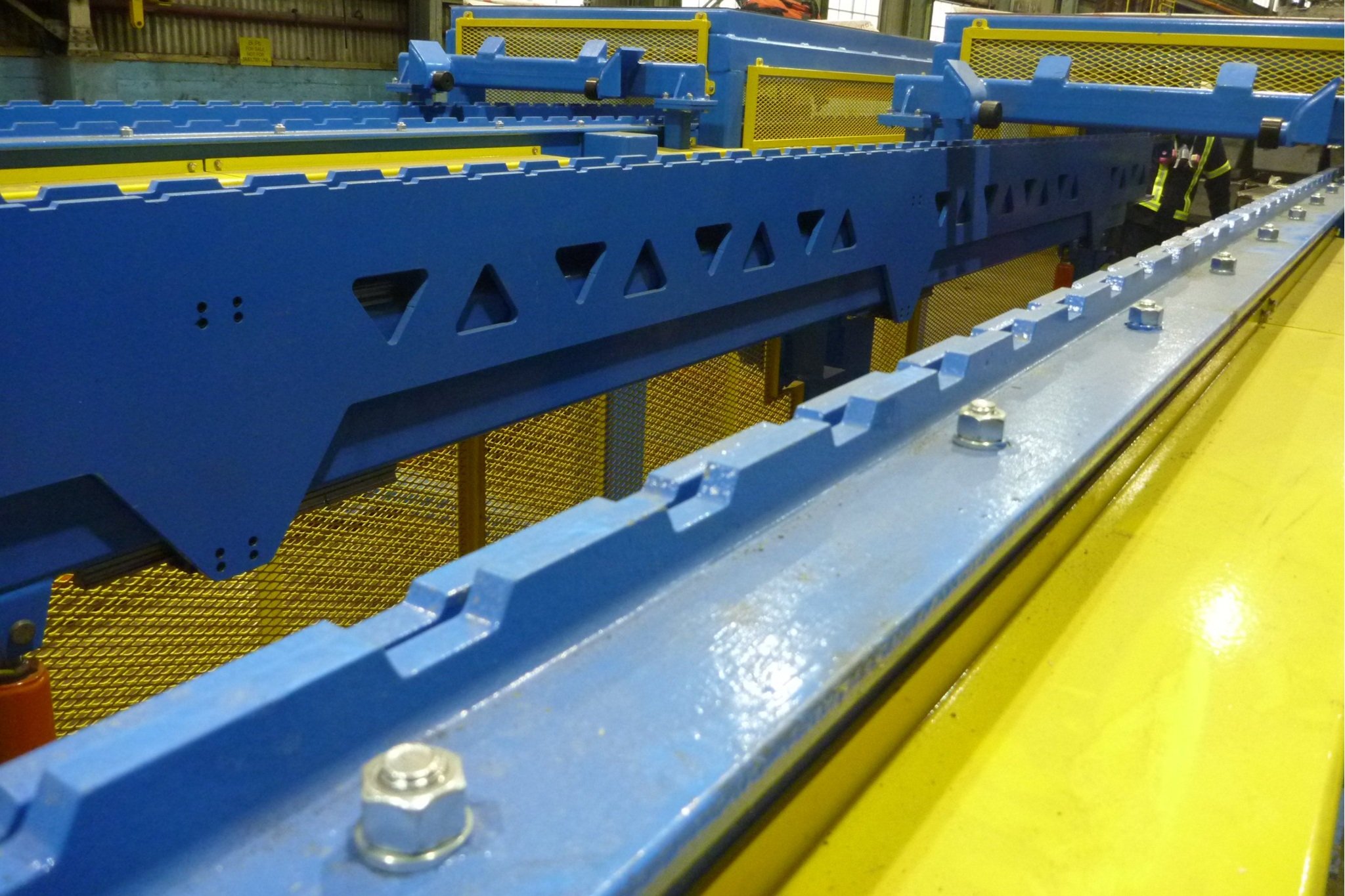
Walking Beam Conveyor
-
Design an automated walking beam that progressively moves 25 cathodes into place for pickup by an overhead crane lifting device.
-
Spacing between cathodes needed to be even
Needed to be automated with very little operator intervention
Required consistent reliability during 24/7 operations
equipment was expected to have a prolonged life with limited down time for maintenance
Conveyor had to line up with existing input and removal equipment
Improve speed of throughput
Easy to maintain simple design
Original conveyor was chain driven and required operator to manually align bars
Process needed to eliminate jamming at all stages
-
The preliminary design required accurate field measurements and 3D modelling to ensure the new equipment would fit with the surrounding pieces. A comb design was utilized to ensure spacing was consistent every time the process ran. The internal comb was mounted on a THK rail and used a single cylinder to move vertical and a single cylinder to move horizontal. The design allowed all wear items to be easily accessed for maintenance and repair. Very little operator intervention was required to run the process and efficiency was improved dramatically.
I/O Design’s licensed trades were on site during installation, completing inspections and assisting in a smooth start-up of the process.
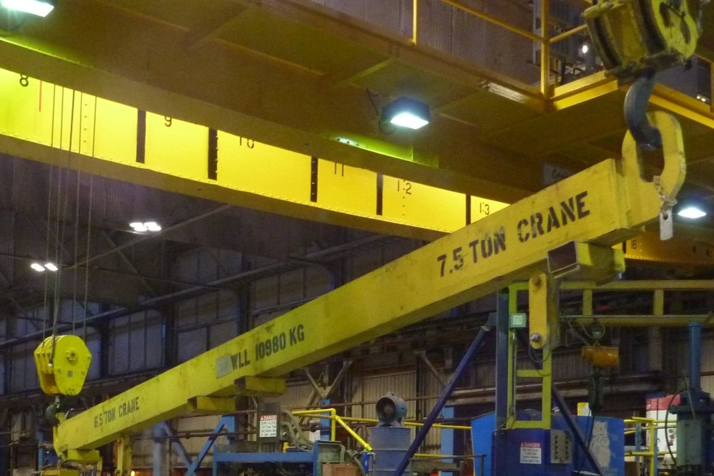
Dual Crane Spreader Beam
-
Design a lifting device to maneuver a lead pot using two overhead bridge cranes in tandem.
-
Minimum distance between cranes sets the length of beam and positions the pot lift points.
Weight of lift beam had to be minimized to allow for a reasonable buildup of lead remaining in pot to be safely lifted.
Weight of lead pot (20,200 lb) had to be distributed between both cranes to avoid exceeding 7.5 Ton crane capacities during lifting, tilting, and rotating operations.
Pot hood also had to be removed using same lifting beam. Extremely low headroom was available for remotely engaging with hood and maneuvering during lift.
-
Field measurements of the minimum crane distances along with a review of the existing lead pot installation drawings aided in developing a conceptual arrangement of the lead pot and hood lift points that allowed for the necessary maneuvering to be safely achieved.
I/O Design optimized the lift beam construction to achieve the strength required based on the position of the loads, while minimizing the weight of the fabricated lifter. This was achieved by selecting a structural steel channel size and joining it together to form a rectangular box-section.
A set of custom hooks was designed to be fabricated from plate steel to achieve a low headroom engagement mechanism for lifting the pot hood without requiring a worker to attach rigging while exposed to a potential fall hazard.

Pot Feeder Test
-
Design a method to test and analyze a mechanism for safely charging a pot of molten lead with a variety of inputs, from 6000 lb lead jumbos to smaller pieces of lead such as scrap anodes.
-
Mechanism needed to work with existing equipment including ventilation hoods, mixing pumps, and pot geometry.
Splashing as the solid pieces of lead enter the molten lead must be minimized, and worker interactions had to be minimized.
Mechanism to be loaded via a forklift.
To establish lead-on-steel and steel-on-steel frictional behavior.
-
I/O Design arranged for a simplified test apparatus to be constructed at a local fabrication shop. We utilized a 100 lb lead block of similar composition but scaled down proportions as the full size jumbos that would be loaded with the actual mechanism. This test apparatus was used to determine the angle at which the payload began to slide, allowing us to determine the coefficient of static friction for lead-on-steel and steel-on-steel. We also wanted to see what the effect was of a transition between steel-on-steel sliding and lead-on-steel sliding, to see if a short section of higher friction sliding could serve to reduce the speed of a lead block prior to furnace entry. We observed that this breakout angle had a tendency to change with repeated tests and further inspection of the lead block revealed that surface condition appeared to exert a significant influence over frictional behavior. Due to the variable surface condition of the various charge materials, frictional behavior would not be sufficiently reliable in service and further work was required to develop a workable concept for this application.